Summary
Below, I will be showing the projects that I have completed during my design courses at UBC as part of my Manufacturing Engineering undergraduate degree.
- Project 1: Thunderdrive RC
Thunderdrive RC Car
What?
This is an 8-month project design course completed during my 3rd year as an Undergraduate Manufacturing Engineering Student at the University of British Columbia. As shown by the title of the project, it was an RC Car project and I was one of 5 team members who worked on the project.
I played a huge role during the project implementation and planning by utilizing transferable skills and knowledge from other courses and being resourceful by conducting external research to introduce data-driven insights, refine design strategies, and optimize the project's overall performance and outcomes.
The objective of this project was to design components and manufacturing processes for a production run of ~20 000 per year for an existing RC car. The components that we mainly focused on were: the wheels, body, and chassis extender/retractor of the car. The overall goals are to keep manufacturability, durability, serviceability, and performance high while keeping costs low and producing an aesthetically appealing car
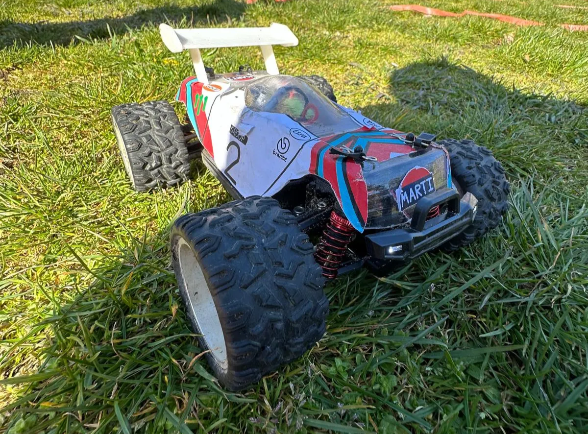
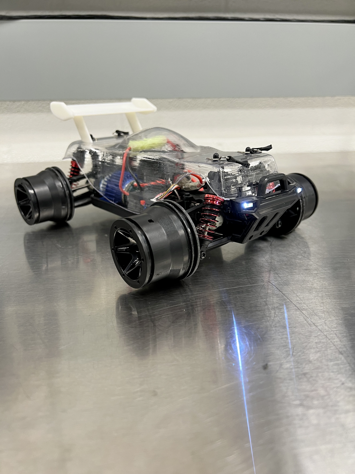
Final RC Car Product
Sub Project 1 - Wheel Design
The first sub-project that I participated in was the wheel re-designing phase where I was responsible for the material selection, cost estimate, and external research phases.
During the material selection phase, the goal was to optimize performance and durability and minimize cost. Due to their weak mechanical properties, plastics were immediately eliminated as metals were the better choice. After narrowing down the metals, Aluminum 6061-T6 was chosen as it aligns with the Design for Manufacturing (DFM) principles, achieves low cost, and its high corrosion resistance that maximizes its reliability especially when encountering off-road terrains with water.
During cost analysis, the price of machines and tools such as CNC machines and their end mill tools were also considered to identify the cost required to manufacture the wheel.
During the External research phase, the wheel design and the machines required to manufacture it were analyzed to convert the design into a tangible product.
After conducting the external research analysis, I observed that the 2-spoke design was the most optimal choice due to its high aerodynamic capabilities which leads to reduced overall drag and its proven success in many competitions such as the Olympics and Paralympics.
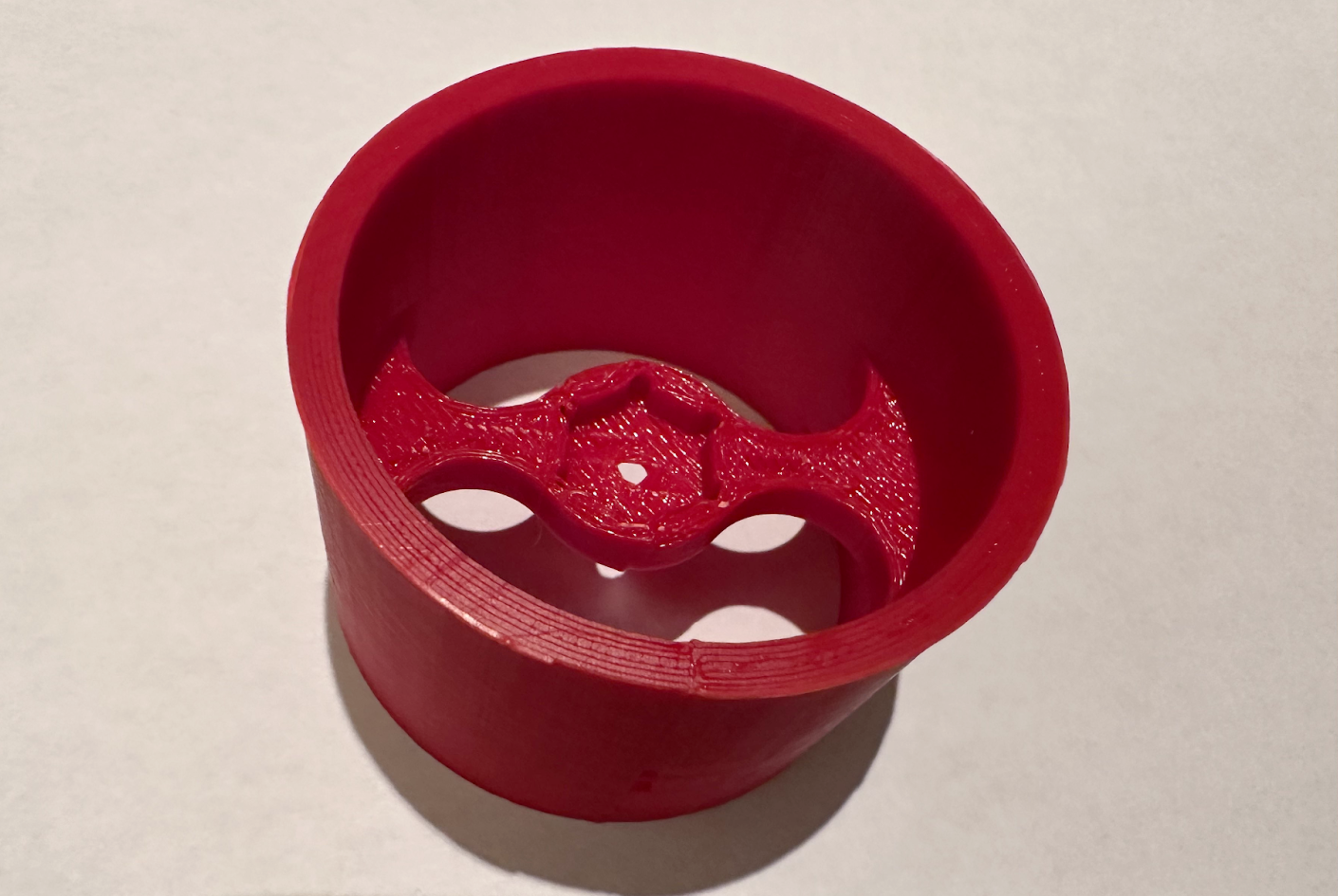
3D-printed wheel used for early testing purposes
Final wheel design with lubrication
 model of the 2-spoke.png)
Front (Left) model of the 2-spoke
Sub Project 2 - Shell Design
During the 2nd sub-project, I focused on the shell design, material selection, and external research.
The 4 main things that came in mind when designing such a component, are its effect on the speed of the car as well, as its durability, aesthetics, durability, and handling. After all our peers completed their sketching designs of the shell, we chose the designs based on an overall agreement within the team. As a result, my idea of creating an oval-shaped top was chosen due to its advantages for building our car. I created that design as it improved the aerodynamics, structural strength, and aesthetics of the car. The rounded shape minimizes the air resistance flowing over the car’s surface, which improves the speed of the RC car and maintains its stability at high speeds. The rounded shell also distributes forces more evenly upon impact, which reduces the risks of deformation or even cracks in the shell. Its look is also physically appealing, giving it a buggy-style look, which is always great when selling to customers and increasing sales.
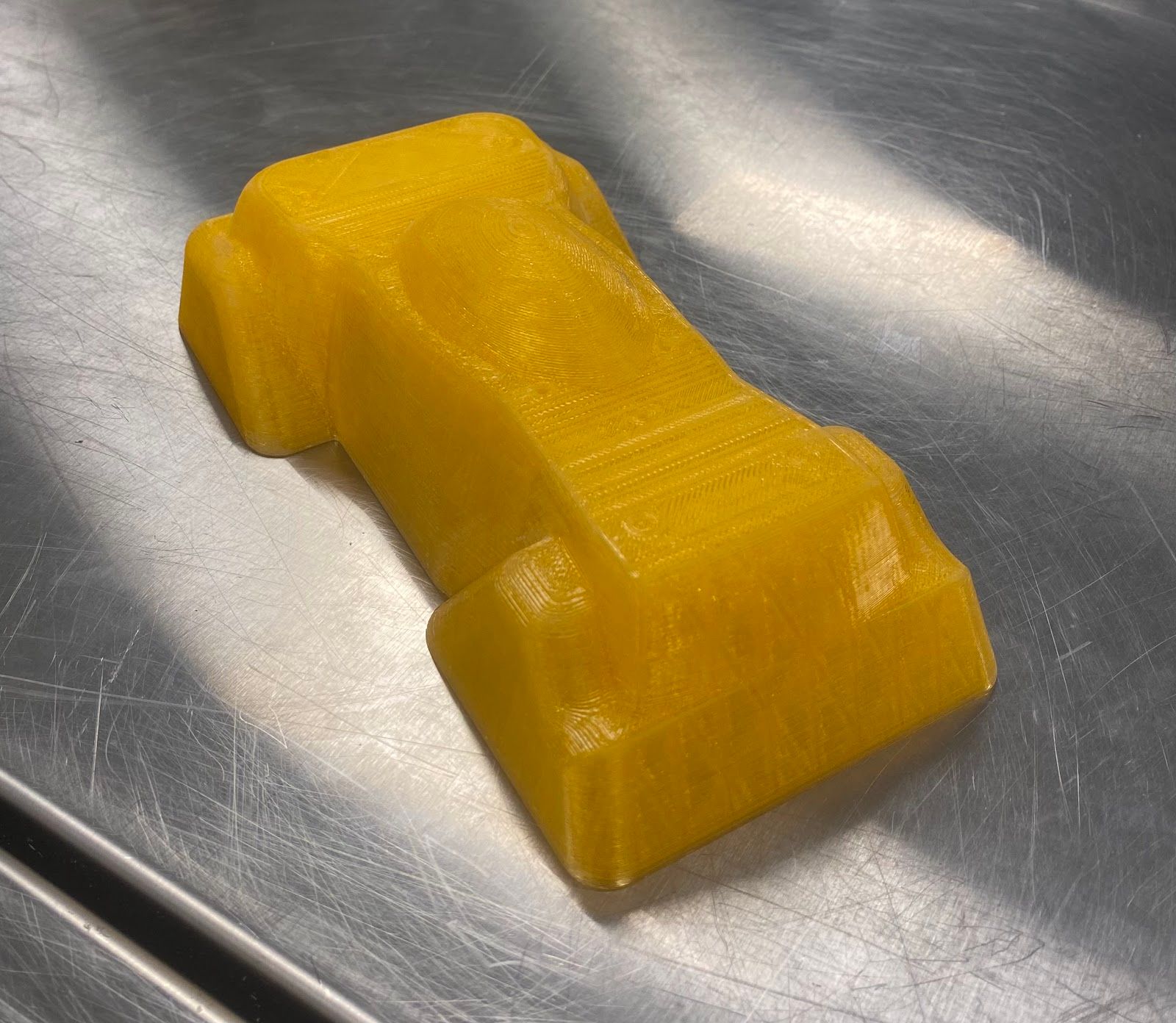
Final shell design printed mould
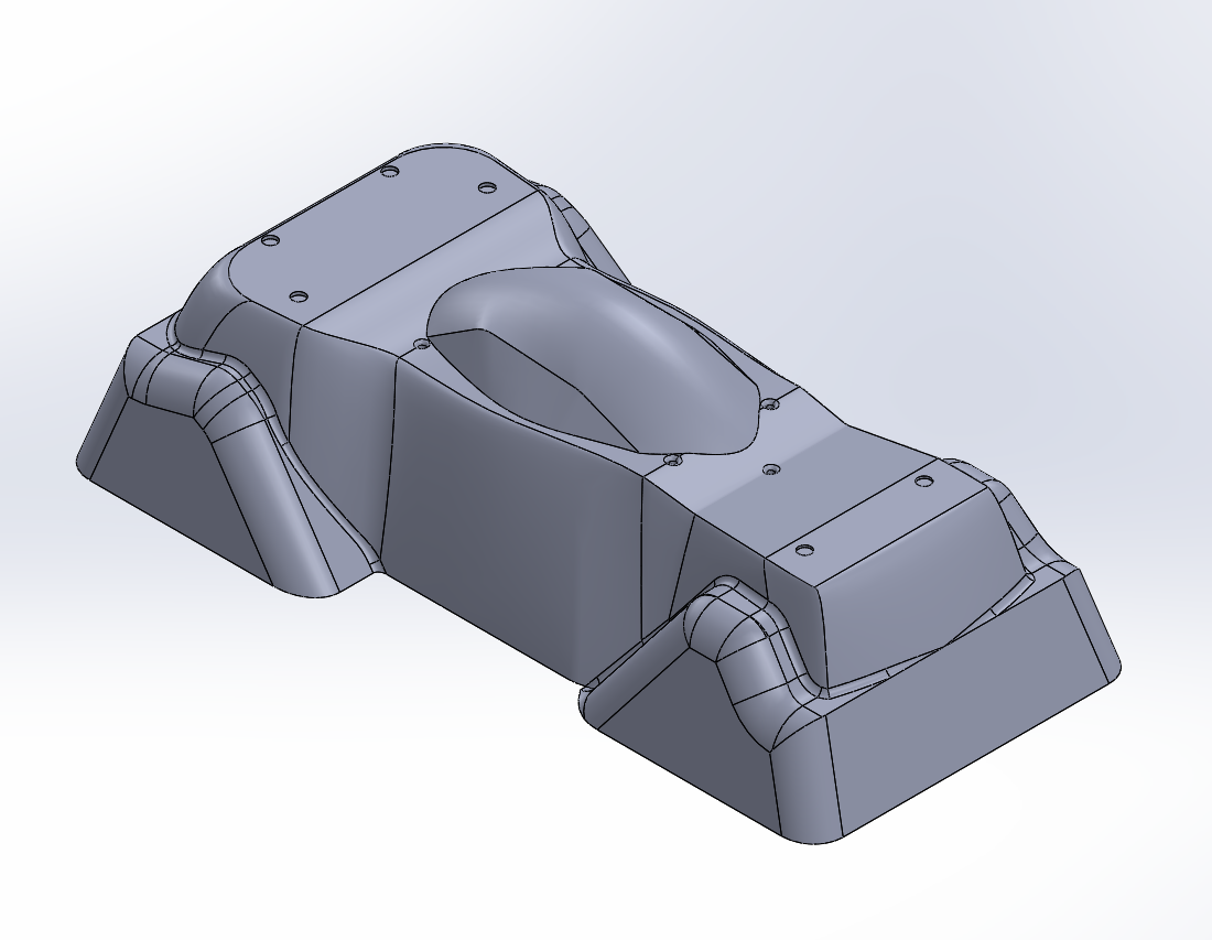
Final shell design CAD model
I conducted an external research analysis to select the best material for the shell. Three materials were considered: Polystyrene, ABS, and PETG. Polystyrene was initially screened out due to its weak structure. Although it is lightweight, which is great for speed performance, it lacks structural integrity as it is too brittle and cannot be used in high-impact activities. ABS and PETG were further analyzed, and PETG was chosen due to its higher durability, overall strength, and tensile strength as well as its transparency allowing for customization.
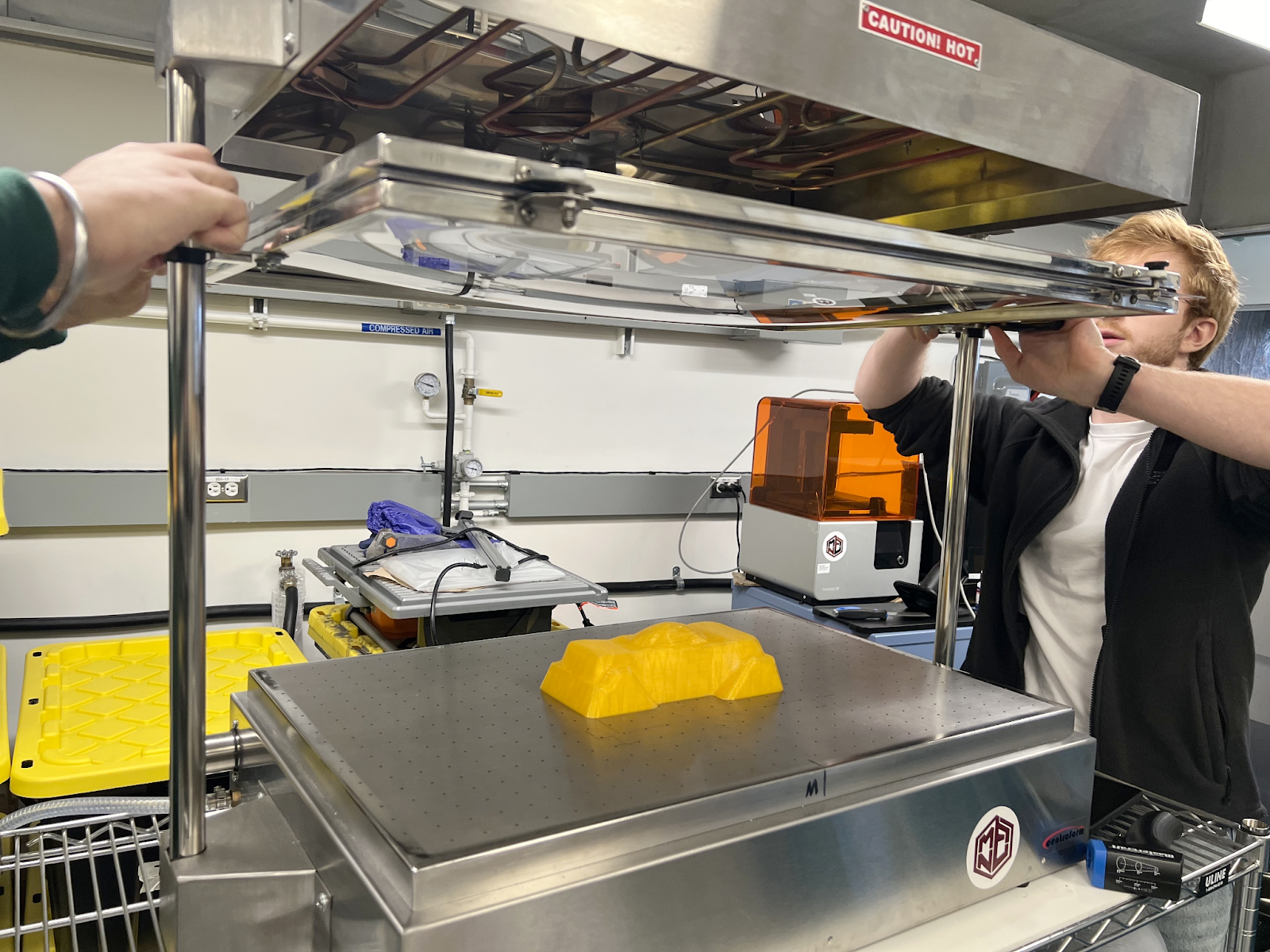
Thermoforming process of shell mould
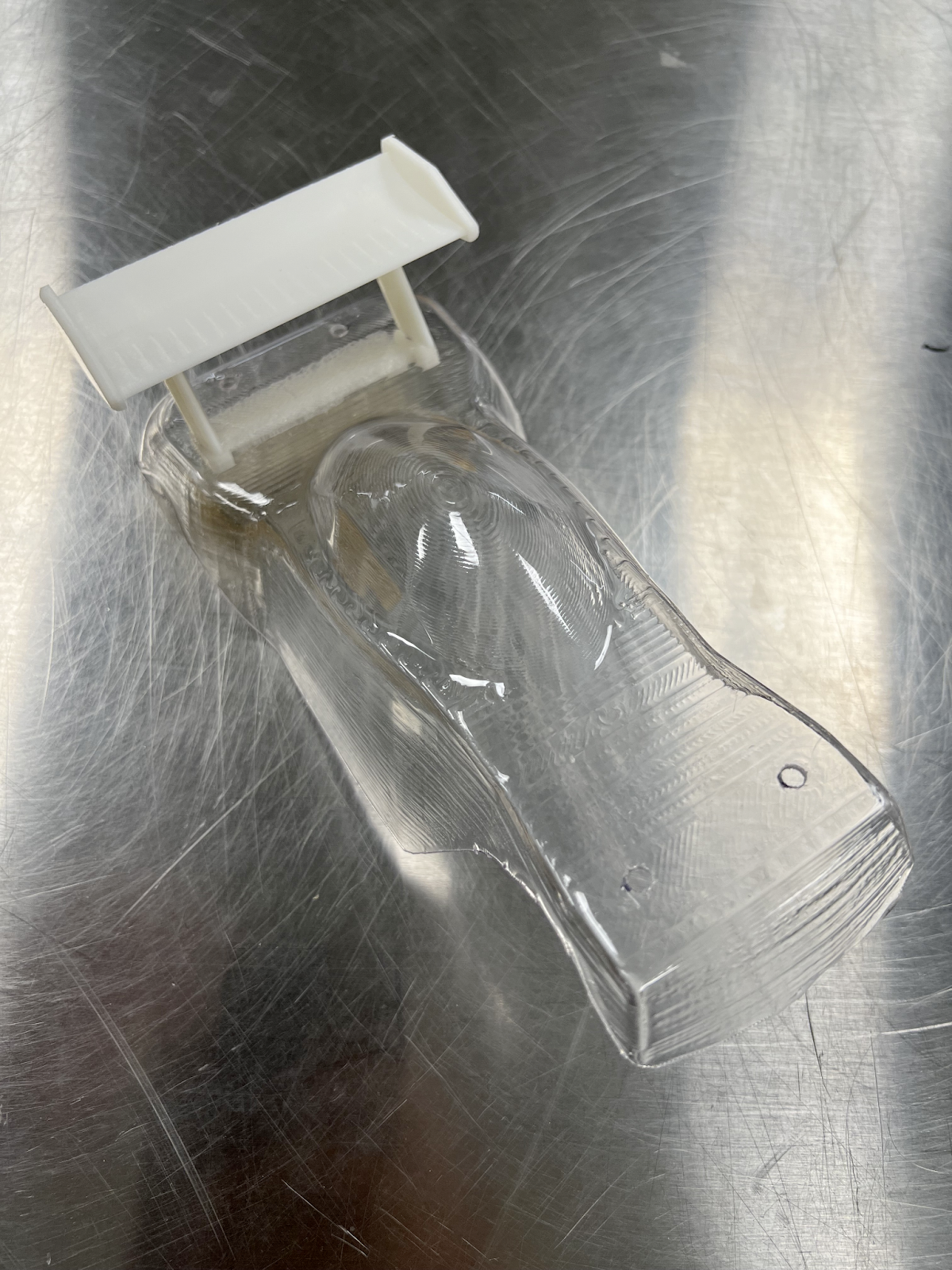
Final PETG thermoformed shell
Check out the links below:
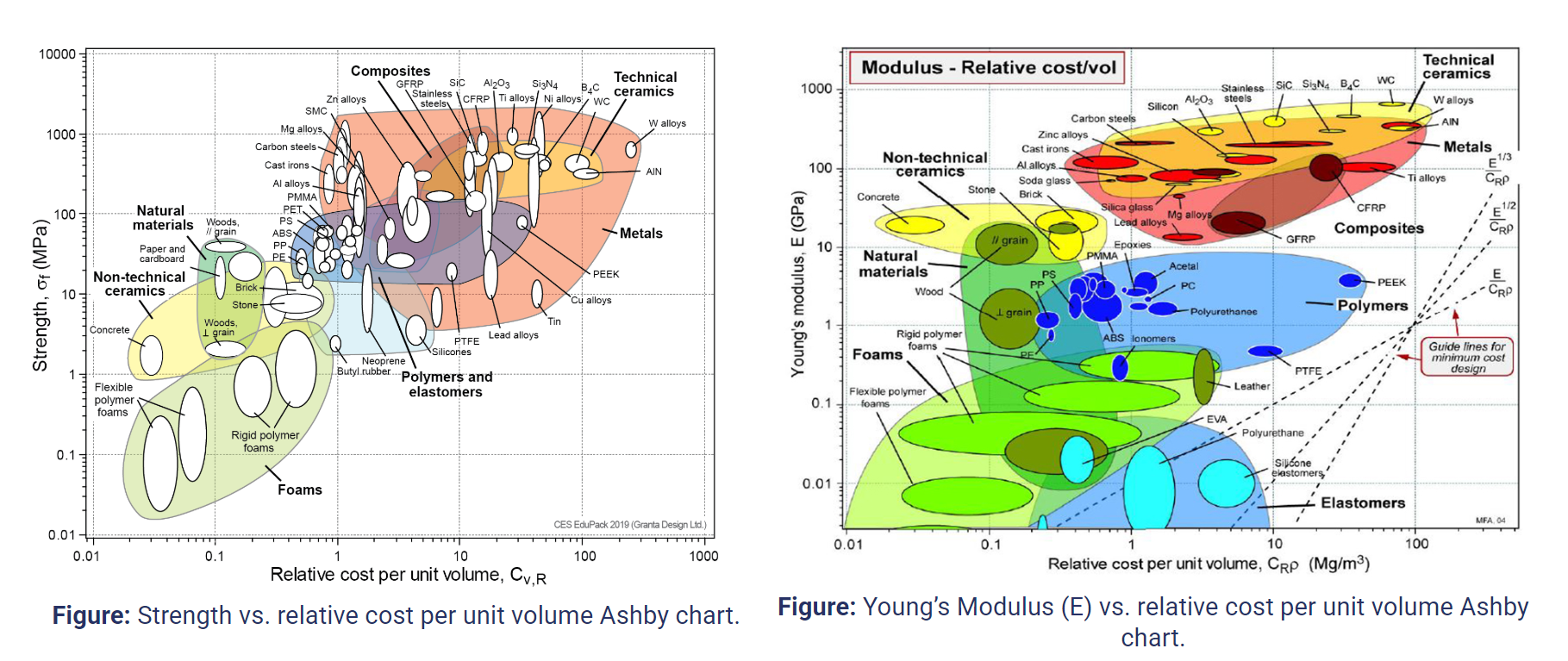
Ashby Charts for the shell
Thermoformed Shell Installed on Chassis
Thermoformed shell installed on chassis
Sub Project 3 - Chassis Design
During the 3rd sub-project, I was responsible for completing some tasks for the chassis. The current chassis component made out of ABS material is to be replaced with composite insert material. Based on stakeholder feedback, the original chassis is to be cut, and an insert is to replace the cut-out part. However, the design of such a cut-out or the material used for the insert is up to us to determine in this project. I worked on the material selection criteria, performing the thermoforming process along with my peers, and conducting an external research analysis.
In the material selection phase, I chose 3 main attributes: high stiffness to provide structural integrity and minimize bending, low weight to enhance speed performance, high strength to provide durability and longevity, and low cost to reduce manufacturing expenses which makes it more affordable for purchasing. Two composite materials were considered: Carbon Fibre and Glass Fibre. I first decided to analyze the cost of both materials. I used the equation C = Cm * m with the objective of minimizing mass to calculate the cost of each material using the dimensions of the chassis. Note: This technique of analyzing the cost of the materials was taught in another class, but I took the initiative of introducing it to this project.
Calculations for cost analysis for Chassis
After completing the cost analysis, I noticed that glass fiber is almost 2 times cheaper than carbon fiber. However, I also noticed that the mass of glass fiber was greater than that of carbon fiber. Because each of the materials satisfied one of the key desired attributes (low weight and low cost), I decided to compare the rest of the attributes. I compared the stiffness and strength properties of both composites relative to their cost using the Ashby Chart.
As a result, I decided to select Carbon Fiber for manufacturing the chassis due to its superior performance in key project objectives. Despite being more expensive than glass fiber, it offers significantly higher stiffness (Young’s modulus) and strength (yield strength) as shown in the Ashby chart. I noticed that these attributes ensure the chassis can withstand greater loads, maintain structural integrity, and resist deformation. Additionally, carbon fiber’s lower density compared to glass fiber enables better speed performance. Therefore, carbon fiber was the obvious better choice due to its combination of high strength, stiffness, and low mass.
In the external research phase, I prioritized a couple of factors: manufacturability, environmental impact, and cost.
Just as my calculations had obtained, research also shows that glass fibre is much cheaper than carbon fiber. I did more research to support the final choice of carbon fiber. Glass fiber allows for a flexible choice of molding processes based on the shape, purpose, and quantity of the property, offering a better overall integrity and excellent manufacturability, however carbon fiber requires precision and specialized techniques making it less manufacturable than glass fiber. Longevity is also a very crucial factor when it comes to purchasing a car, and according to the majority of sources, both are corrosion resistant, however carbon fiber was proven to have a higher corrosion resistance and making it a better for purchasing for long term use. Speed is very important for our car, and therefore, I noticed that carbon fiber has 15% less weight than glass fiber, which means that CFRP could contribute to the high speed performance for our RC car. Based on many sources, glass fiber is mostly used in applications that require electrical insulation, which is very unnecessary in our case.
Carbon fiber is more commonly used in the racing industry; for instance in bicycles it is usually used for bicycle frames and in chassis in Formula 1 cars as well due to their high strength–weight ratio, high modulus-to-weight ratio, high aesthetic, and quick maneuvering due to its low weight. Glass fiber is used also in the automotive industry, but it is more commonly used as a front bumper due to its high strength and flexibility. However, we also know that CFRP is stronger than GFRP, and our objective is to have higher stiffness rather than high flexibility. Therefore, it was clear to me that CFRP is the better material to be used for our chassis.
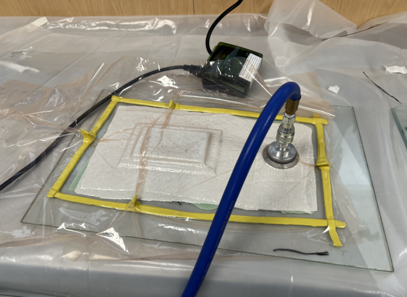
After analyzing multiple processes available to us at the laboratory, we chose the wet layup process combined with vacuum bagging the part to allow the composite material to shape the exact form of the male mould. The following showcases the vacuumed part after selecting six layers of composite wet layup materials and vacuuming.
 >
>
Wet-layup composite during the vacuuming process
After demolding the carbon fiber part, we proceeded to cut and sand it. However, note that due to its concave shape, it did not fit the original chassis. Therefore, excess material was cut from the composite to remove the excess material and fit it on the original.
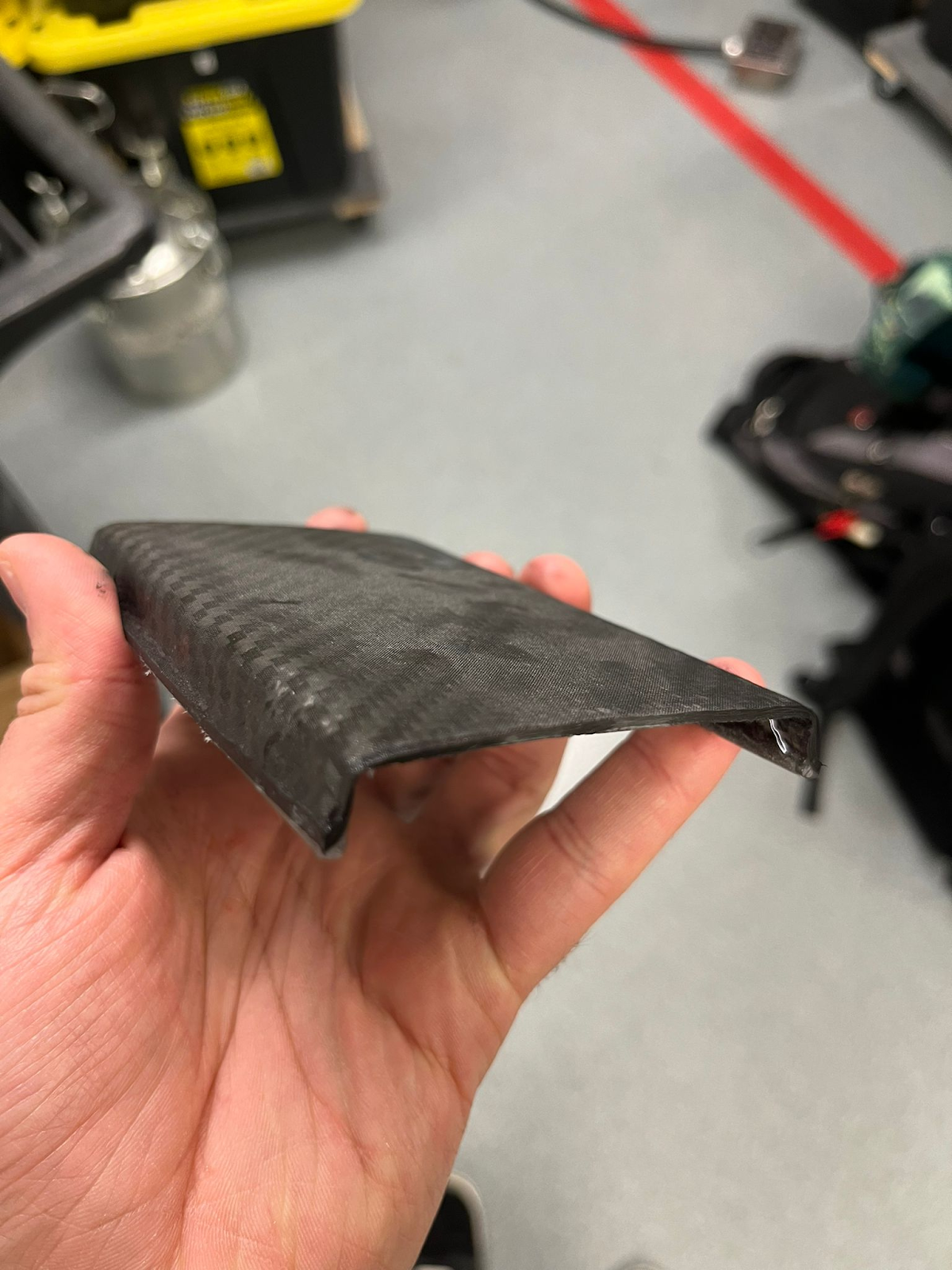
Wet-layup composite after demolding
.png)
Wet-layup composite attached to the chassis
What?
This is an 8-month project design course completed during my 3rd year as an Undergraduate Manufacturing Engineering Student at the University of British Columbia. As shown by the title of the project, it was an RC Car project and I was one of 5 team members who worked on the project.
I played a huge role during the project implementation and planning by utilizing transferable skills and knowledge from other courses and being resourceful by conducting external research to introduce data-driven insights, refine design strategies, and optimize the project's overall performance and outcomes.
The objective of this project was to design components and manufacturing processes for a production run of ~20 000 per year for an existing RC car. The components that we mainly focused on were: the wheels, body, and chassis extender/retractor of the car. The overall goals are to keep manufacturability, durability, serviceability, and performance high while keeping costs low and producing an aesthetically appealing car
Final RC Car Product
Sub Project 1 - Wheel Design
The first sub-project that I participated in was the wheel re-designing phase where I was responsible for the material selection, cost estimate, and external research phases.
During the material selection phase, the goal was to optimize performance and durability and minimize cost. Due to their weak mechanical properties, plastics were immediately eliminated as metals were the better choice. After narrowing down the metals, Aluminum 6061-T6 was chosen as it aligns with the Design for Manufacturing (DFM) principles, achieves low cost, and its high corrosion resistance that maximizes its reliability especially when encountering off-road terrains with water.
During cost analysis, the price of machines and tools such as CNC machines and their end mill tools were also considered to identify the cost required to manufacture the wheel.
During the External research phase, the wheel design and the machines required to manufacture it were analyzed to convert the design into a tangible product.
After conducting the external research analysis, I observed that the 2-spoke design was the most optimal choice due to its high aerodynamic capabilities which leads to reduced overall drag and its proven success in many competitions such as the Olympics and Paralympics.
3D-printed wheel used for early testing purposes
Final wheel design with lubrication
Front (Left) model of the 2-spoke
Sub Project 2 - Shell Design
During the 2nd sub-project, I focused on the shell design, material selection, and external research.
The 4 main things that came in mind when designing such a component, are its effect on the speed of the car as well, as its durability, aesthetics, durability, and handling. After all our peers completed their sketching designs of the shell, we chose the designs based on an overall agreement within the team. As a result, my idea of creating an oval-shaped top was chosen due to its advantages for building our car. I created that design as it improved the aerodynamics, structural strength, and aesthetics of the car. The rounded shape minimizes the air resistance flowing over the car’s surface, which improves the speed of the RC car and maintains its stability at high speeds. The rounded shell also distributes forces more evenly upon impact, which reduces the risks of deformation or even cracks in the shell. Its look is also physically appealing, giving it a buggy-style look, which is always great when selling to customers and increasing sales.
Final shell design printed mould
Final shell design CAD model
I conducted an external research analysis to select the best material for the shell. Three materials were considered: Polystyrene, ABS, and PETG. Polystyrene was initially screened out due to its weak structure. Although it is lightweight, which is great for speed performance, it lacks structural integrity as it is too brittle and cannot be used in high-impact activities. ABS and PETG were further analyzed, and PETG was chosen due to its higher durability, overall strength, and tensile strength as well as its transparency allowing for customization.
Thermoforming process of shell mould
Final PETG thermoformed shell
Check out the links below:
Ashby Charts for the shell
Thermoformed Shell Installed on Chassis
Thermoformed shell installed on chassis
Sub Project 3 - Chassis Design
During the 3rd sub-project, I was responsible for completing some tasks for the chassis. The current chassis component made out of ABS material is to be replaced with composite insert material. Based on stakeholder feedback, the original chassis is to be cut, and an insert is to replace the cut-out part. However, the design of such a cut-out or the material used for the insert is up to us to determine in this project. I worked on the material selection criteria, performing the thermoforming process along with my peers, and conducting an external research analysis.
In the material selection phase, I chose 3 main attributes: high stiffness to provide structural integrity and minimize bending, low weight to enhance speed performance, high strength to provide durability and longevity, and low cost to reduce manufacturing expenses which makes it more affordable for purchasing. Two composite materials were considered: Carbon Fibre and Glass Fibre. I first decided to analyze the cost of both materials. I used the equation C = Cm * m with the objective of minimizing mass to calculate the cost of each material using the dimensions of the chassis. Note: This technique of analyzing the cost of the materials was taught in another class, but I took the initiative of introducing it to this project.
Calculations for cost analysis for Chassis
After completing the cost analysis, I noticed that glass fiber is almost 2 times cheaper than carbon fiber. However, I also noticed that the mass of glass fiber was greater than that of carbon fiber. Because each of the materials satisfied one of the key desired attributes (low weight and low cost), I decided to compare the rest of the attributes. I compared the stiffness and strength properties of both composites relative to their cost using the Ashby Chart.
As a result, I decided to select Carbon Fiber for manufacturing the chassis due to its superior performance in key project objectives. Despite being more expensive than glass fiber, it offers significantly higher stiffness (Young’s modulus) and strength (yield strength) as shown in the Ashby chart. I noticed that these attributes ensure the chassis can withstand greater loads, maintain structural integrity, and resist deformation. Additionally, carbon fiber’s lower density compared to glass fiber enables better speed performance. Therefore, carbon fiber was the obvious better choice due to its combination of high strength, stiffness, and low mass.
In the external research phase, I prioritized a couple of factors: manufacturability, environmental impact, and cost.
Just as my calculations had obtained, research also shows that glass fibre is much cheaper than carbon fiber. I did more research to support the final choice of carbon fiber. Glass fiber allows for a flexible choice of molding processes based on the shape, purpose, and quantity of the property, offering a better overall integrity and excellent manufacturability, however carbon fiber requires precision and specialized techniques making it less manufacturable than glass fiber. Longevity is also a very crucial factor when it comes to purchasing a car, and according to the majority of sources, both are corrosion resistant, however carbon fiber was proven to have a higher corrosion resistance and making it a better for purchasing for long term use. Speed is very important for our car, and therefore, I noticed that carbon fiber has 15% less weight than glass fiber, which means that CFRP could contribute to the high speed performance for our RC car. Based on many sources, glass fiber is mostly used in applications that require electrical insulation, which is very unnecessary in our case.
Carbon fiber is more commonly used in the racing industry; for instance in bicycles it is usually used for bicycle frames and in chassis in Formula 1 cars as well due to their high strength–weight ratio, high modulus-to-weight ratio, high aesthetic, and quick maneuvering due to its low weight. Glass fiber is used also in the automotive industry, but it is more commonly used as a front bumper due to its high strength and flexibility. However, we also know that CFRP is stronger than GFRP, and our objective is to have higher stiffness rather than high flexibility. Therefore, it was clear to me that CFRP is the better material to be used for our chassis.
After analyzing multiple processes available to us at the laboratory, we chose the wet layup process combined with vacuum bagging the part to allow the composite material to shape the exact form of the male mould. The following showcases the vacuumed part after selecting six layers of composite wet layup materials and vacuuming.
>
Wet-layup composite during the vacuuming process
After demolding the carbon fiber part, we proceeded to cut and sand it. However, note that due to its concave shape, it did not fit the original chassis. Therefore, excess material was cut from the composite to remove the excess material and fit it on the original.
Wet-layup composite after demolding
Wet-layup composite attached to the chassis
This is an 8-month project design course completed during my 3rd year as an Undergraduate Manufacturing Engineering Student at the University of British Columbia. As shown by the title of the project, it was an RC Car project and I was one of 5 team members who worked on the project.
I played a huge role during the project implementation and planning by utilizing transferable skills and knowledge from other courses and being resourceful by conducting external research to introduce data-driven insights, refine design strategies, and optimize the project's overall performance and outcomes.
The objective of this project was to design components and manufacturing processes for a production run of ~20 000 per year for an existing RC car. The components that we mainly focused on were: the wheels, body, and chassis extender/retractor of the car. The overall goals are to keep manufacturability, durability, serviceability, and performance high while keeping costs low and producing an aesthetically appealing car
Sub Project 1 - Wheel Design
The first sub-project that I participated in was the wheel re-designing phase where I was responsible for the material selection, cost estimate, and external research phases.
During the material selection phase, the goal was to optimize performance and durability and minimize cost. Due to their weak mechanical properties, plastics were immediately eliminated as metals were the better choice. After narrowing down the metals, Aluminum 6061-T6 was chosen as it aligns with the Design for Manufacturing (DFM) principles, achieves low cost, and its high corrosion resistance that maximizes its reliability especially when encountering off-road terrains with water.
During cost analysis, the price of machines and tools such as CNC machines and their end mill tools were also considered to identify the cost required to manufacture the wheel.
During the External research phase, the wheel design and the machines required to manufacture it were analyzed to convert the design into a tangible product.
After conducting the external research analysis, I observed that the 2-spoke design was the most optimal choice due to its high aerodynamic capabilities which leads to reduced overall drag and its proven success in many competitions such as the Olympics and Paralympics.
Sub Project 2 - Shell Design
During the 2nd sub-project, I focused on the shell design, material selection, and external research.
The 4 main things that came in mind when designing such a component, are its effect on the speed of the car as well, as its durability, aesthetics, durability, and handling. After all our peers completed their sketching designs of the shell, we chose the designs based on an overall agreement within the team. As a result, my idea of creating an oval-shaped top was chosen due to its advantages for building our car. I created that design as it improved the aerodynamics, structural strength, and aesthetics of the car. The rounded shape minimizes the air resistance flowing over the car’s surface, which improves the speed of the RC car and maintains its stability at high speeds. The rounded shell also distributes forces more evenly upon impact, which reduces the risks of deformation or even cracks in the shell. Its look is also physically appealing, giving it a buggy-style look, which is always great when selling to customers and increasing sales.
I conducted an external research analysis to select the best material for the shell. Three materials were considered: Polystyrene, ABS, and PETG. Polystyrene was initially screened out due to its weak structure. Although it is lightweight, which is great for speed performance, it lacks structural integrity as it is too brittle and cannot be used in high-impact activities. ABS and PETG were further analyzed, and PETG was chosen due to its higher durability, overall strength, and tensile strength as well as its transparency allowing for customization.
Check out the links below:
Ashby Charts for the shell
Thermoformed Shell Installed on Chassis
Thermoformed shell installed on chassis
Sub Project 3 - Chassis Design
During the 3rd sub-project, I was responsible for completing some tasks for the chassis. The current chassis component made out of ABS material is to be replaced with composite insert material. Based on stakeholder feedback, the original chassis is to be cut, and an insert is to replace the cut-out part. However, the design of such a cut-out or the material used for the insert is up to us to determine in this project. I worked on the material selection criteria, performing the thermoforming process along with my peers, and conducting an external research analysis.
In the material selection phase, I chose 3 main attributes: high stiffness to provide structural integrity and minimize bending, low weight to enhance speed performance, high strength to provide durability and longevity, and low cost to reduce manufacturing expenses which makes it more affordable for purchasing. Two composite materials were considered: Carbon Fibre and Glass Fibre. I first decided to analyze the cost of both materials. I used the equation C = Cm * m with the objective of minimizing mass to calculate the cost of each material using the dimensions of the chassis. Note: This technique of analyzing the cost of the materials was taught in another class, but I took the initiative of introducing it to this project.
Calculations for cost analysis for Chassis
After completing the cost analysis, I noticed that glass fiber is almost 2 times cheaper than carbon fiber. However, I also noticed that the mass of glass fiber was greater than that of carbon fiber. Because each of the materials satisfied one of the key desired attributes (low weight and low cost), I decided to compare the rest of the attributes. I compared the stiffness and strength properties of both composites relative to their cost using the Ashby Chart.
As a result, I decided to select Carbon Fiber for manufacturing the chassis due to its superior performance in key project objectives. Despite being more expensive than glass fiber, it offers significantly higher stiffness (Young’s modulus) and strength (yield strength) as shown in the Ashby chart. I noticed that these attributes ensure the chassis can withstand greater loads, maintain structural integrity, and resist deformation. Additionally, carbon fiber’s lower density compared to glass fiber enables better speed performance. Therefore, carbon fiber was the obvious better choice due to its combination of high strength, stiffness, and low mass.
In the external research phase, I prioritized a couple of factors: manufacturability, environmental impact, and cost.
Just as my calculations had obtained, research also shows that glass fibre is much cheaper than carbon fiber. I did more research to support the final choice of carbon fiber. Glass fiber allows for a flexible choice of molding processes based on the shape, purpose, and quantity of the property, offering a better overall integrity and excellent manufacturability, however carbon fiber requires precision and specialized techniques making it less manufacturable than glass fiber. Longevity is also a very crucial factor when it comes to purchasing a car, and according to the majority of sources, both are corrosion resistant, however carbon fiber was proven to have a higher corrosion resistance and making it a better for purchasing for long term use. Speed is very important for our car, and therefore, I noticed that carbon fiber has 15% less weight than glass fiber, which means that CFRP could contribute to the high speed performance for our RC car. Based on many sources, glass fiber is mostly used in applications that require electrical insulation, which is very unnecessary in our case.
Carbon fiber is more commonly used in the racing industry; for instance in bicycles it is usually used for bicycle frames and in chassis in Formula 1 cars as well due to their high strength–weight ratio, high modulus-to-weight ratio, high aesthetic, and quick maneuvering due to its low weight. Glass fiber is used also in the automotive industry, but it is more commonly used as a front bumper due to its high strength and flexibility. However, we also know that CFRP is stronger than GFRP, and our objective is to have higher stiffness rather than high flexibility. Therefore, it was clear to me that CFRP is the better material to be used for our chassis.
After analyzing multiple processes available to us at the laboratory, we chose the wet layup process combined with vacuum bagging the part to allow the composite material to shape the exact form of the male mould. The following showcases the vacuumed part after selecting six layers of composite wet layup materials and vacuuming.
>
After demolding the carbon fiber part, we proceeded to cut and sand it. However, note that due to its concave shape, it did not fit the original chassis. Therefore, excess material was cut from the composite to remove the excess material and fit it on the original.